- Home
- Popular IT Certifications
- Troubleshoot OSPF Path Preference & OSPF for IPv6
How to troubleshoot OSPF path preference, OSPF operations and OSPF for IPv6
Course inclination is utilized to choose which course is introduced in the sending table when a few conventions figure courses to the same goal. The course with the least inclination worth is chosen. Naturally, inner OSPF courses have an inclination estimation of 10, and outside OSPF courses have an inclination estimation of 150. You may need to alter this setting on the off chance that you want to relocate from OSPF to an alternate IGP. Altering the course inclination empowers you to perform the relocation in a controlled way.
This case makes the accompanying presumptions:
OSPF is as of now running in your system. You need to move from OSPF to IS-IS. You arranged IS-IS for every your system prerequisites and affirmed it is working legitimately. In this case, you build the OSPF course inclination qualities to make them less favored than IS-IS course by determining 168 for interior OSPF courses and 169 for outside OSPF courses. IS-IS inward courses have an inclination of either 15 (for Level1) or 18 (for Level 2), and outer courses have an inclination of 160 (for Level 1) or 165 (for Level 2). All in all, it is wanted to leave the new convention at its default settings to minimize complexities and rearrange any future expansion of steering gadgets to the system. To change the OSPF course inclination qualities, design the accompanying settings:
Inclination: Specifies the course inclination for interior OSPF courses. Naturally, inward OSPF courses have an estimation of 10. The extent is from 0 through 4,294967,295 (232 - 1).
Outside inclination: Specifies the course inclination for outer OSPF courses. Of course, outer OSPF courses have an estimation of 15.
Route calculation for OSPF
The steering estimation procedure of the OSPF convention is as takes after:
Each OSPF-competent switch keeps up a Link State Database (LSDB), which depicts the topology of the entire AS. As per the system topology around itself, every switch creates a Link State Advertisement (LSA). The switches on the system transmit the LSAs among them by transmitting the convention parcels to every other. In this manner, every switch gets the LSAs of different switches and all these LSAs make its LSDB.
LSA portrays the system topology around a switch, so the LSDB depicts the system topology of the entire system. Switches can without much of a stretch change the LSDB to a weighted guided chart, which really reflects the topology building design of the entire system. Clearly, all the switches get a chart precisely the same. A switch utilizes the SPF calculation to figure the briefest way tree with itself as the root, which demonstrates the courses to the hubs in the self-sufficient framework. The outer steering data is the leave hub. A switch, which publicizes the courses, likewise labels them and records the extra data of the self-governing framework. Clearly, the steering tables got by distinctive switches are diverse.
Moreover, to empower singular switches to telecast their nearby state data to the whole AS, any two switches in nature's turf ought to secure nearness between them. For this situation, then again, the changes that any switch takes will bring about various transmissions, which are unnecessary as well as waste the valuable transmission capacity assets. To take care of this issue, "Assigned Router" (DR) is characterized in the OSPF. Consequently, all the switches just send data to the DR for TV the system connection states in the system. Subsequently, the quantity of switch contiguous relations on the multi-access system is lessened. OSPF helps interface-based bundle validation to ensure the security of course estimation. Additionally, it transmits and gets parcels by IP multicast (224.0.0.5 and 224.0.0.6).
Router ID and area
To run OSPF, a switch must have a switch ID. On the off chance that no ID is designed, OSPF naturally picks a switch ID arranged for the switch or an IP location of the switch interfaces as the ID of the OSPF switch. A switch ID is chosen as takes after. On the off chance that the switch is designed with a switch ID, this switch ID is utilized as the switch ID of the OSPF switch. In the event that no switch ID is arranged and loopback interfaces' locations exist, the framework picks the most elevated IP address as the switch ID. In the event that no Loopback interface is arranged, then the most astounding IP address among physical interfaces' locations will be the switch ID. On the off chance that different OSPF courses of action exist, distinctive techniques will choose diverse switch Ids. The system size develops progressively bigger. On the off chance that all the switches on an immense system are running OSPF, the extensive number of switches will bring about a colossal LSDB, which will devour a gigantic storage room, confuse the SPF calculation, and include the CPU stack too. Besides, as a system develops bigger, the topology gets to be more prone to take changes. Subsequently, the system will dependably be in "turbulence", and a lot of OSPF parcels will be created and transmitted in the system. This will bring down the system data transfer capacity utility. What's more, each one change will result in all the courses on the system to recalculate the course.
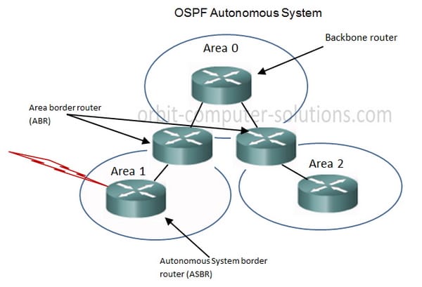
OSPF takes care of the above issue by parcel an AS into distinctive territories. Ranges are coherent gatherings of switches. The outskirts of territories are framed by switches. Along these lines, a few switches may have a place with diverse territories. A switch joins the spine range and a non-spine zone is called Area Border Router (ABR). An ABR can unite with the spine zone physically or sensibly.
OSPF operations
This area depicts how to empower an Ospfv2 transform on the ASA. After you empower Ospfv2, you have to characterize a course outline. For more data, see the "Characterizing a Route Map" area. At that point you produce a default course. For more data, see the "Designing Static and Default Routes" area.
After you have characterized a course outline the Ospfv2 process, you can modify it for your specific needs, to figure out how to alter the Ospfv2 transform on the ASA, see the "Redoing Ospfv2" area. To empower Ospfv2, you have to make an Ospfv2 steering procedure, tag the scope of IP locations connected with the directing methodology, then dole out zone Ids connected with that scope of IP locations. You can empower up to two Ospfv2 methodology examples. Every Ospfv2 process has it related zones and systems. You can change some interface-particular Ospfv2 parameters, if vital. You are not needed to change any of these parameters, however the accompanying interface parameters must be predictable over all switches in a joined system: OSPF hi interim, OSPF dead-interim, and OSPF verification key. On the off chance that you arrange any of these parameters, make certain that the designs for all switches on your system have good values.
Configuring OSPF
OSPF arrangement needs collaboration among switches: intra-territory, region limit, and AS limit. In the event that none of OSPF parameters is arranged, their default settings apply. For this situation, sent and got bundles are not confirmed, and an individual interface does not fit in with the territory of any AS. At the point when reconfiguring a default parameter on one switch, verify that the same change is made on all other included switches. In different arrangements, you should first empower OSPF, indicate the interface and range ID before arranging different capacities. However the setup of the capacities identified with the interface is not confined by whether the OSPF is empowered or not. It ought to be noted that after OSPF is crippled, the OSPF-related interface parameters additionally get to be invalid.
A switch ID is a 32-bit unsigned number in IP location design that interestingly distinguishes a switch inside an AS. A switch ID could be arranged physically. In the event that no switch ID is designed, the framework will choose the IP location of an interface naturally. When you do that physically, you must ensure that the Ids of any two switches in the AS are remarkable. A typical undertaking is to situate the switch ID to be the IP location of an interface on the switch. In the wake of utilizing the OSPF summon to empower OSPF in framework view, you must indicate the system to run OSPF. An ABR switch might be in diverse ranges, while a system portion can just fit in with a zone. That is, you must point out a particular territory for each one port running OSPF. OSPF can import the outside steering data and telecast it to the whole independent framework. Importing courses time after time and importing an excess of outer courses at one time will enormously influence the execution of the gadget. Thusly it is important to define the default interim and number for the convention to import outside courses. On the off chance that a switch transmits a Link State Advertisements (LSA) to the companion, it requires the acknowledgement bundle from the associate. On the off chance that it doesn't get the acknowledgement parcel inside the retransmit time, it will retransmit this LSA to the neighbor. The estimation of retransmit is client configurable.
OSPF for IPv6
An expansive OSPF system may oblige a short yet substantial blast of transmission capacity as LSAs are traded. Once the LSAs are traded a lot of memory is obliged to hold the LSDB before meeting. Running the SPF calculation obliges high CPU usage. Systems with much of the time showing up and vanishing connections may cause execution issues on any switch due to the three-stage LSA era, holding the LSDB, and running the SPF process. The overhead and execution issues of OSPF could be minimized by separating the OSPF AS into ranges.
For a NBMA system, some unique designs are needed. Since a NBMA interface on the system can't find the neighboring switch through TV Hello bundles, you should physically point out an IP address for the adjoining switch for the interface, and define whether the contiguous switch is qualified for race.
Interface priority and the DR selection
The need of a switch interface decides the capability of the interface in DR race. The switch with the need of 0 can't be chosen as the DR or BDR. DR is not assigned physically. Rather, it is chosen by all the switches on the portion. Votes are hi bundles. Every switch composes the normal DR in the parcel and sends it to the various switches on the section. On the off chance that two switches connected to the same fragment simultaneously proclaim themselves to be the DR, pick the unified with higher need. On the off chance that the needs are the same, pick the unified with more prominent switch ID. On the off chance that the need of a switch is 0, it won't be chosen as DR or BDR.
On the off chance that DR falls flat because of a few blames, the switches on the system must choose another DR and synchronize with the new DR. The procedure will take a moderately long time, amid which, the course figuring is off base. So as to accelerate this procedure, OSPF advances the idea of BDR. Indeed, BDR is reinforcement for DR. DR and BDR are chosen meanwhile. The adjacencies are likewise settled between the BDR and all the switches on the fragment, and steering data is additionally traded between them. At the point when the DR comes up short, the BDR will turn into the DR in a split second. Since no re-race is required and the adjacencies have as of now been created, the methodology is short. However for this situation, another BDR ought to be chosen. In spite of the fact that it will likewise take a long time of time, it won't push any impact upon the course computation.
The DR on the system is not so much the switch with the most elevated need. Similarly, the BDR is not so much the switch with the second most noteworthy need. In the event that another switch is included after DR and BDR decision, it is incomprehensible for the switch to turn into the DR regardless of the possibility that it has the most noteworthy need. DR is focused around the switch interface in a certain section. Possibly a switch is a DR on one interface, however could be a BDR on an alternate interface. DR decision is needed for the telecast or NBMA interfaces. For the p2p or p2mp interfaces, DR race is not needed.


Site Search:


